The Mate to the Mighty Midget
This is my version of the Mate to the Mighty Midget originally designed by McCoy and appeared in QST Magazine in April 1966. I have modified it a bit by adding a 6AQ5 at the end of the AF chain to give the audio a bit of ooph. The original was ok for head phone use but I wanted a bit of extra volume to I could use a speaker and this set up gives me enough audio to copy moderately loud stations. The schematics can be seen here. I have redone them with my own capture program and have added my own changes and additions. Please note that these schematics are my copyright although the design is not.
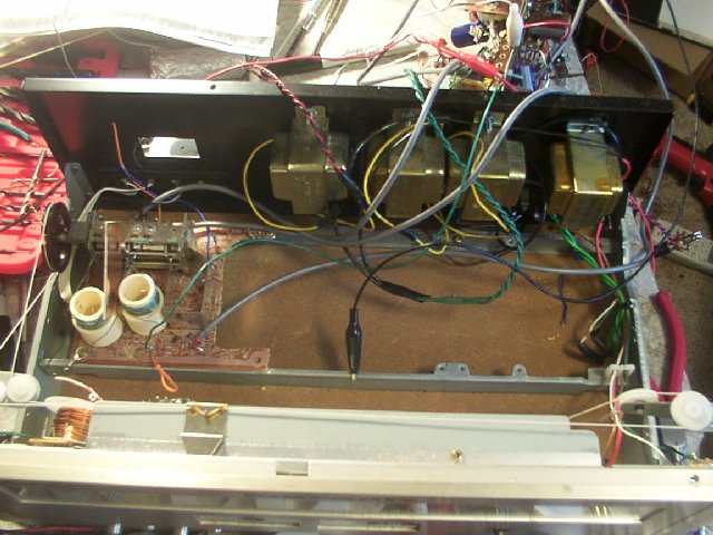
Here is another picture of the chassis and cabinet after I ripped out the guts and added the transformers. This was originally a Morantz that I picked up at an auction for free. The guy who bought a box of stuff didn't want this particular piece so I begged it off him. Note that I left the original tuning caps as the MMRX article called for a ganged 365pF variable and from the size and plate space I think this one comes close, it seems to tune about right anyway. The power transformers can be seen mounted at the top. From left to right they are the 6.3v filament transformer, back to back 12.6v 1.2amp transformers that form the HV portion and lastly an unknown transformer that came with the unit and powers the lights and leds on the front panel. The slide rule tuning device still functions so that works well with the finished product.
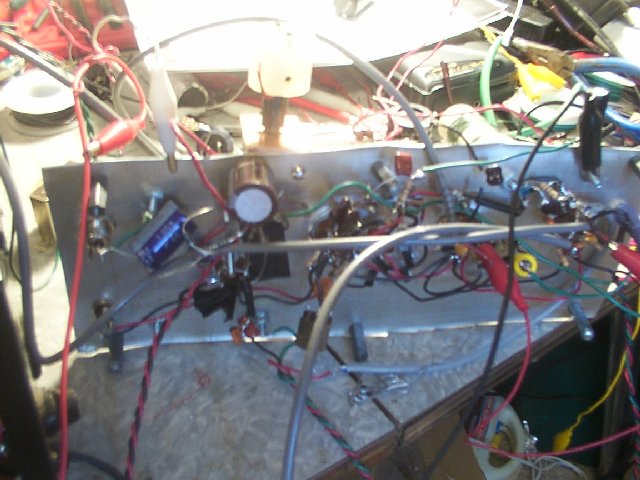
Here is another picture of genius in progress.
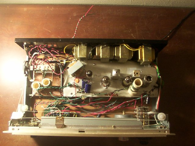
Here is a picture of the final product. You can see the tube line up from left to right is the 6AQ5 and then V3, V2, and V1.
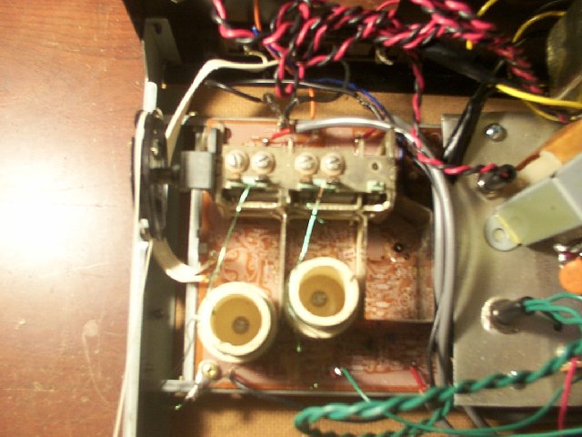
This is a close up of the original variable cap with my coils mounted. This piece alone saved me who knows how much time it tracks like a champ. All I did was rip out the old coils and add my own. I had to adjust it very little to get it to track on both 80m and 40m.
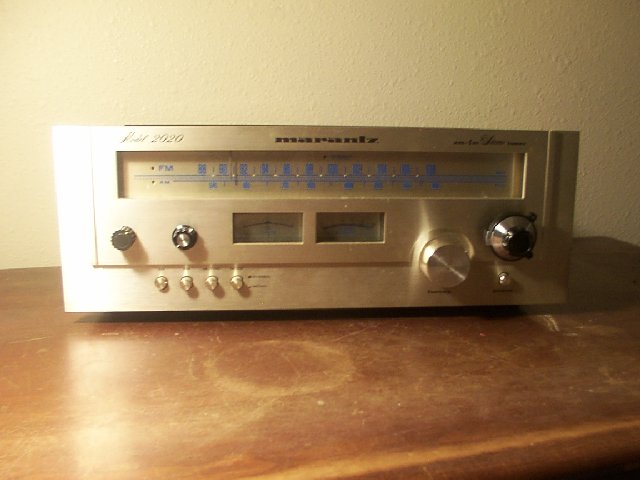
This is a front picture of the radio I made the following mods to the front panel. the gain is the knob on middle left. The volume is the one next to the gain and on the middle right you can see the main tuning planetary knob. At present I am not using the meters but I eventually would like add an S-meter so they may get used yet. I also incorporated the two push buttons on the lower left. When the far left is pushed I get 40m and when the next one to it is pressed I get 80 meters.
Here is the coil information:
L1 consists of fine close spaced turns directly below L2 and the two windings have no space between them. Be sure that the turns are put on in the same direction. L3 and L4 are duplicates of L1 and L2.
The high frequency coils are also close wound and must also be wound in the same direction or the oscillator will not oscillate. The diagram of the coil below shows the proper way to wrap it.
I used 1/2 inch I.D. PVC tubing for all of the coils.
The complete article can be found here
This is EB5AGV web page. I have not asked his permission to link to it so I have disabled a direct link. However if you copy and paste this address into your address bar it should take you to his page.
Questions? Comments? rhaub@swiftel.net